Introduction
Back home, my parents had these electric blinds installed in the house. Both windows in my bedroom had these two battery powered motors controlled by an RF remote to bring the blinds up and down. These were installed well before the IoT revolution hit the mainstream market, so the blinds were not connected to any hubs or WiFi or anything else that could control them apart from the RF remotes assigned to each room. This summer when I came home for college, I decided to use a little bit of my college education to make my room 'connected'.
The Idea
Raspberry Pis are such versatile, impressive, and most importantly cheap computers. In college, I had one plugged into my dorm room ethernet as a local document server, and was able to access it anywhere while on campus WiFi by an IP address routed through DNS to a domain I owned. It wasn't available everywhere, but anytime I was on campus, I could access documents directly through a shortlink from any computer, which proved particularly useful when I needed to use campus computers for our free printing quotas.
I won another Raspberry Pi during an on campus hackathon in freshman year, so when I came home for the summer this year, I figured I could use that to build out some connected features in my room. The first thing I did was turn it into a ShairPort device, which let me wirelessly play music on an old pair of powered speakers from my iPod and iPhone.
I wanted to be able to control my blinds without needing to use the remote control. I figured if I did it through some kind of script, I could use it to set alarms and have my room wake me up with natural light.
The Execution
Supplies and Setup
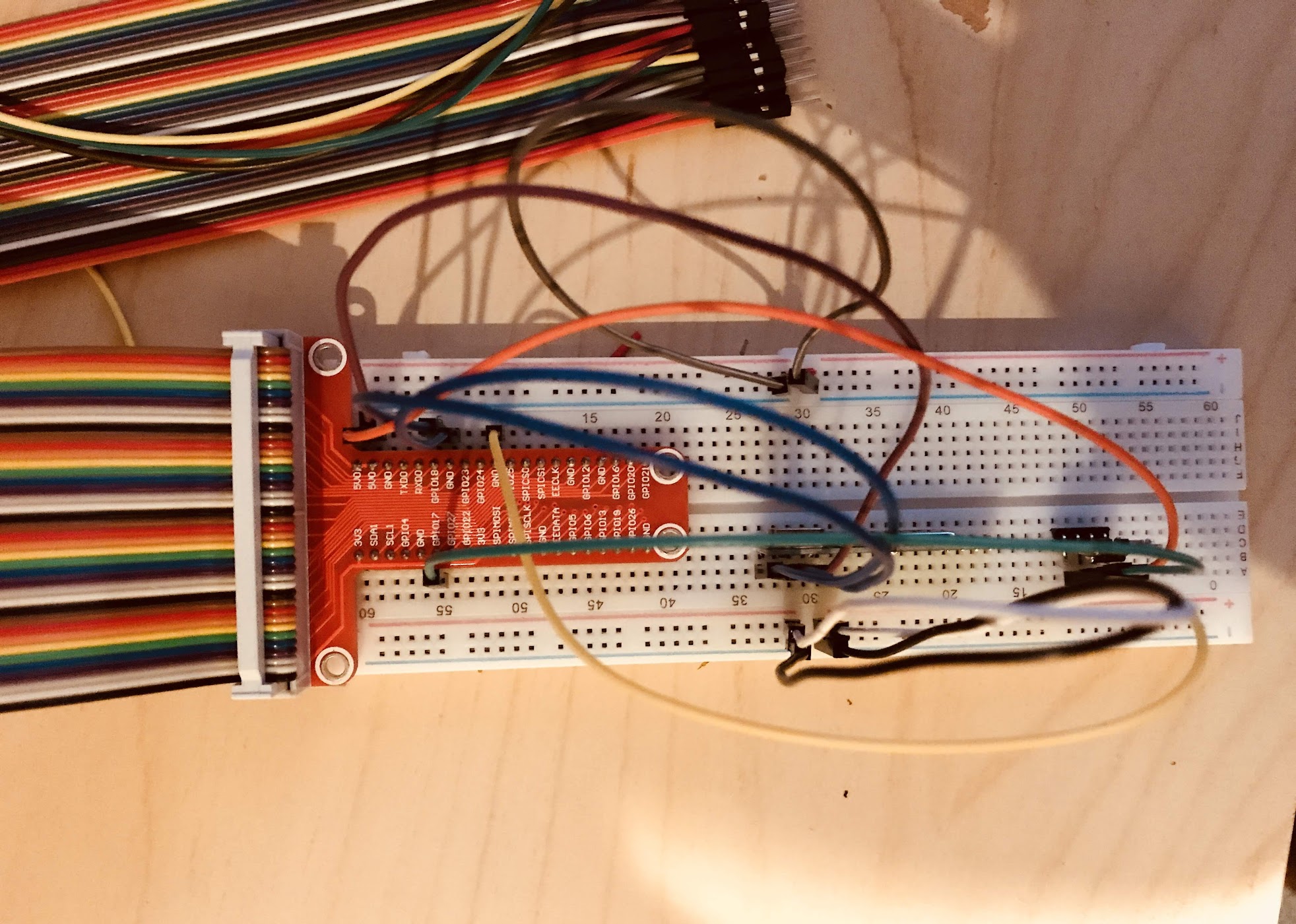
I bought a breadboard and some simple pins and wires on Amazon, and then bought a 433 MHz RF receiver and an RF transmitter, also from Amazon. The last thing I bought was a GPIO breadboard adapter to help me visualize the ports on the Raspberry Pi as they interacted with the breadboard. While there are ways to simplify the circuitry, I stuck with the breadboard and GPIO adapter for the final product. GPIO stands for General Purpose Input Output, which is basically an interface that allows the Raspberry Pi to interact with external circuitry while supplying power and enabling the transfer of data.
I followed the labels on the transmitter and receiver to wire them to the ground, the power (5V) and the data I/O ports. The final setup is visible in the picture below.
Writing the Code
The code is distributed into a few parts.
1. Reading and saving the signal
2. Transmitting the signal with fidelity
3. A script with parameters to have the Raspberry Pi transmit on demand.
The zero step is setting up basic GPIO settings on the raspberry pi: import RPi.GPIO as GPIO and setting a global variable with the Transmit and Receive Pins on the board. 17 and 27 respectively for me. A great diagram can be found here
1. Reading and saving the signal
from datetime import datetime
import RPi.GPIO as GPIO
import pickle
I decided to use pickle to save the arrays of data. Text files could also have been used, but pickles allowed me to dump and read directly into python arrays instead of worrying about parsing.
RECEIVED_SIGNAL = [[], []]  #[[time of reading], [signal reading]]
MAX_DURATION = 5
RECEIVE_PIN = 27

if __name__ == '__main__':
    GPIO.setmode(GPIO.BCM)
    GPIO.setup(RECEIVE_PIN, GPIO.IN)
    cumulative_time = 0
    beginning_time = datetime.now()
    print '**Started recording**'
    while cumulative_time < MAX_DURATION:
        time_delta = datetime.now() - beginning_time
        RECEIVED_SIGNAL[0].append(time_delta)
        RECEIVED_SIGNAL[1].append(GPIO.input(RECEIVE_PIN))
        cumulative_time = time_delta.seconds
    print '**Ended recording**'
    print len(RECEIVED_SIGNAL[0]), 'samples recorded'
    GPIO.cleanup()

    print '**Processing results**'
    for i in range(len(RECEIVED_SIGNAL[0])):
        RECEIVED_SIGNAL[0][i] = RECEIVED_SIGNAL[0][i].seconds + RECEIVED_SIGNAL[0][i].microseconds/1000000.0

    with open('temp.pkl', 'w') as f:
        pickle.dump(RECEIVED_SIGNAL, f)
    f.close()
The code above is how I tracked the signal at different points in time and just kept reading data. Then to verify I was getting a continuous signal, I wanted to plot the signal before trying to replicate it. It looked like this in matplotlib.

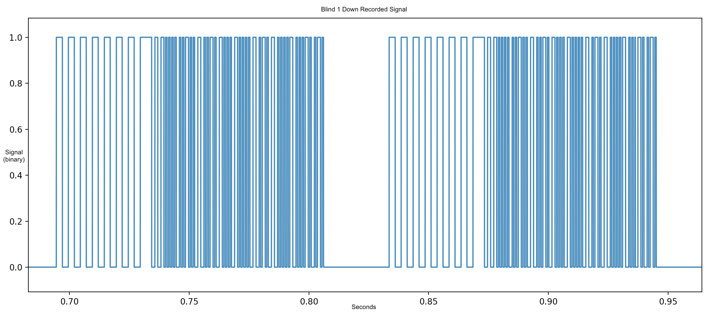
The first picture is 2 whole seconds of me holding down the button for one direction of one blind on the remote. The second picture is a zoomed in detail view of two full transmission periods of the signal. The signal repeats itself often to ensure the receiver on the motor has a chance of accepting the command without dropping the signal.
2. Transmitting the signal with fidelity
After getting the up and down codes for both blinds (4 codes in total), it was time to use the transmitter to replicate the signal. Here, I define the mapping of commands to the relevant pickle files.
NUM_ATTEMPTS = 2
TRANSMIT_PIN = 17
path = "/home/pi/PyBlinds/codes/"
dict = {"up": ['b1_up_code.pkl', 'b2_up_code.pkl'], "down":['b1_down_code.pkl', 'b2_down_code.pkl']}
Next, it was a simple for loop of repeating the signal a few times just to make sure that the signal goes through because I ran into issues with the signal not going through when there was just one attempt.
def transmit_code(pkl):
    '''Transmit a chosen code string using the GPIO transmitter'''
    print("Transmitting %s" % path+pkl)
    with open(path + pkl, 'rb') as f:
        code = pickle.load(f)
    GPIO.setmode(GPIO.BCM)
    GPIO.setup(TRANSMIT_PIN, GPIO.OUT)
    for t in range(NUM_ATTEMPTS):
        for v, d in code:
            GPIO.output(TRANSMIT_PIN, v)
            time.sleep(d)
    GPIO.cleanup()
The last part was writing an input mapping function to choose which pickle file(s) to use, but that wasn't too complex. It was just a quick if statement for inputs about which blinds to move and which directions to move them.
def main(direction, blind=0):
    d = dict[direction]
    if(blind==0):
        transmit_code(d[0])
        transmit_code(d[1])
    elif(blind==1):
        transmit_code(d[0])
    elif(blind==2):
        transmit_code(d[1])

if __name__ == '__main__':
    dir = str(sys.argv[1])
    blind = 0
    if(len(sys.argv) > 2):
        blind = int(sys.argv[2])
    main(dir, blind)
3. A script with parameters to have the Raspberry Pi transmit on demand.
Putting the script onto the Raspberry Pi just involved using sftp to put the pickle files and the python files into the right directories on the machine.
The main shell script was called operate.sh and looks like this:
#! /bin/sh
sudo python3 /home/pi/PyBlinds/transmit.py $1 $2
The first parameter is the direction (up or down), and the second is which blinds (0 for both, 1 for blind 1 only, and 2 for blind 2 only)
Usability and Impacts
Phase One
Initially, I set up a cron job to raise and lower the blinds, but the issue I ran into was that on some days I wake up at different times, or want to sleep in, or just don't want the job to run. Using SSH to control these jobs was too painstaking, so instead I wrote a simple (unsecure) PHP script that would let me click a button for an action from a webpage. I deployed an nginx server to the Raspberry Pi so it could host an HTML/PHP page only on the local network. Since my home WiFi network was secured, only someone with the local IP address and on the network could access the webpage. This was good enough, and I added the link to my iPhone home screen, so it functioned kind of like a web app.
Phase Two
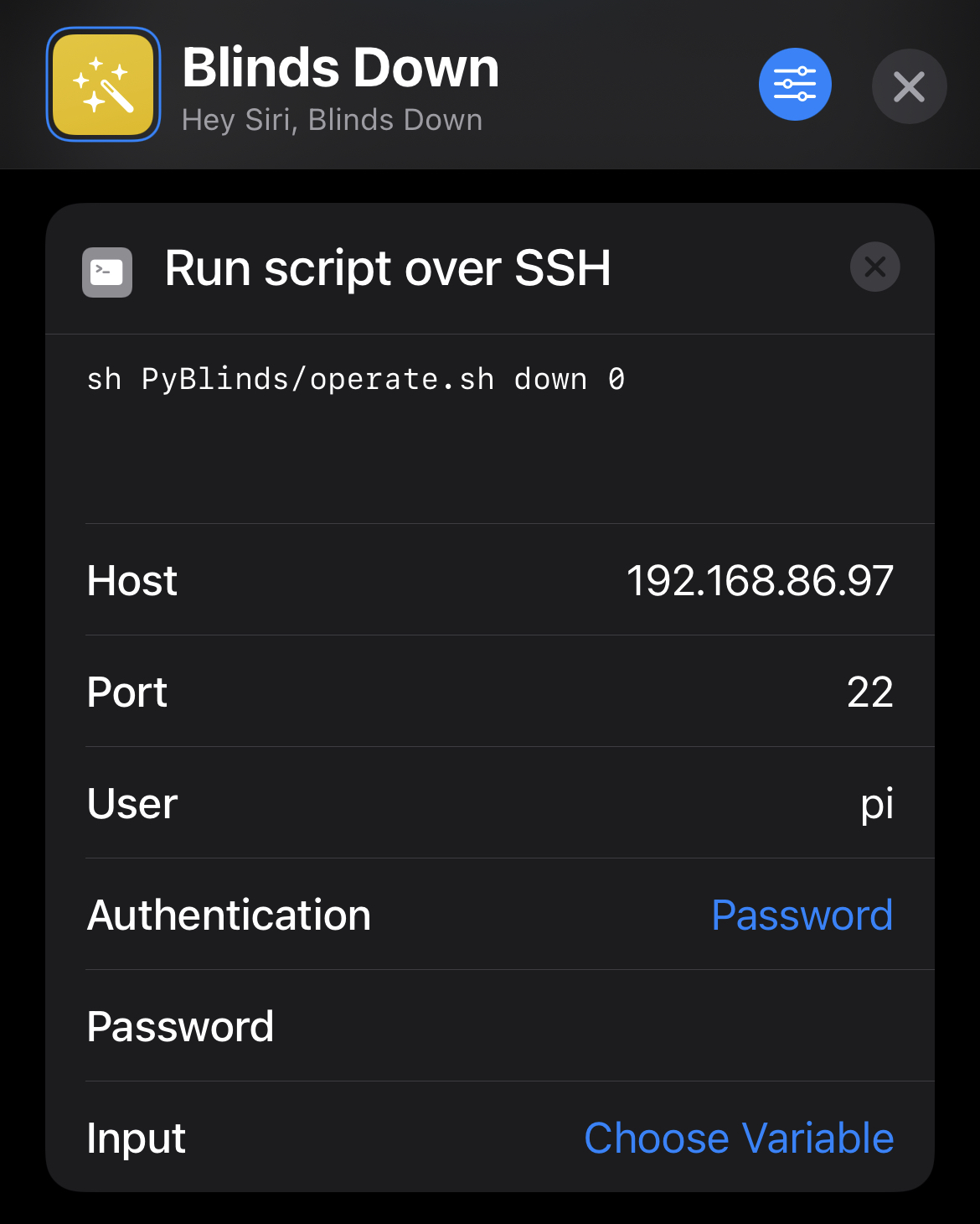
In the later summer of 2018, I downloaded the Apple Shortcuts app, which allowed for scripting functionality. In that scripting functionality, I was able to run commands over ssh on remote devices. This worked really well because once again, the local IP ssh was only accessible on the local network.
A shortcut called Blinds Up supplied the up parameter to the script and sends the command to the raspberry pi. A parallel shortcut called Blinds Down supplied the down parameter. Now, in 2021 with automations available in the Shortcuts app, I have the shortcuts tied to my wakeup alarm with a location filter, so if I'm home and snooze my alarm, the blinds go up.
Impact
Overall it was a pretty simple project, but it allowed me to exercise my skills in circuits and hardware, while also building remote control interfaces over RF, SSH, and a connected home device that I had wanted for a long time. I'm a big believer in adapting technology instead of replacing technology. Replacing all the blinds in my parents' house with connected systems on WiFi would have been prohibitively expensive and wasteful of money and the original product we had installed. Instead, using a little bit of engineering and some inexpensive tools, I was able to build out a connected home with no privacy concerns and little to no new funds.